The ejector EO - 30m is a jet pump with two compression stages, designed to remove uncondensed gases from the steam space of the turbine and network heaters, as well as to suck steam from the turbine seals in order to maintain a constant vacuum in the steam condenser.
Symbol for the main steam jet ejector EO - 30m:
EO - base ejector;
30 — performance of the ejector in terms of steam - air mixture, kg/h
m - modernized
Product composition
The scope of delivery of the main steam jet ejector EO - 30m includes the following
components:
- Main steam jet ejector EO - 30m;
- Control and measuring equipment.
Specifications of the ejector:
| No. p / p | Characteristic name | Dimension | Meaning |
| one | Number of steps | PCS | 2 |
| 2 | PVA performance | kg/h | 31.6 |
| 3 | PVA temperature | about C | 25 |
| four | Working steam consumption, no more | kg/h | 156 |
| 5 | Working steam temperature in front of the nozzle | about C | 170 - 250 |
| 6 | Absolute pressure of working steam in front of the nozzle, not less than | MPa (Kgf / cm 2 ) | 1.6 (16) |
| 7 | Condensate flow rate | M 3 /h | eighteen |
| eight | Working pressure of the cooling condensate, no more | MPa (Kgf / cm 2 ) | 1.47 (15) |
| 9 | Hydraulic resistance against condensate | KPa (Kgf / cm 2 ) | 30 (0.3) |
| ten | Number of coolers | PCS | 2 |
| eleven | Number of condensate passes in each cooler | PCS | 2 |
| 12 | Number of tubes in each cooler | PCS | 192 |
The principle of operation of the EO ejector - 30m
Steam with pressure is supplied to the nozzle box of the EO - 30m ejector through a steam pipeline,
exceeding the pressure of the vapor - air mixture. Steam is supplied to the 1st and 2nd stage nozzles through
angle valves along the steam line (the steam line is not included in the scope of delivery of the ejector) pos. I
connection tables.
The nozzle of the 1st stage is located in the body of the nozzle chamber (mixing chamber) of the 1st stage,
the nozzle of the 2nd stage is located in the body of the nozzle chamber (mixing chamber) of the 2nd stage.
At the same time, into the suction chambers through a specially designed outlet (pos. II
connection table) steam - air mixture is supplied. The vapor - air mixture enters
through the corresponding outlet
In the nozzle box, steam and steam - air mixture are mixed, which, under
under the influence of the flows created by the nozzles, rushes into the diffusers of the corresponding
steps. At the outlet of the diffusers, the pressure of the vapor - air mixture slightly increases.
После дифффузоров паровоздушная смесь попадает в корпус эжектора. В корпусе водяной
пар конденсируется на теплообменных трубах 1го и 2го холодильников и выводится через
соответствующие отводы (поз. VI Таблицы присоединений). Несконденсировавшийся воздух
выводится из корпуса эжектора через отвод поз. V таблицы присоединений.
По водяной части.
Подвод/отвод охлаждающей воды осуществляется через соответствующие подводы,
находящиеся в нижней части водяных камер (поз. III таблицы присоединений).
Охлаждающая вода поступает через подводящий патрубок, соединенный с соответствующим
фланцем в нижней части водяной камеры. Охлаждающая вода с температурой не выше 20º С
через подводящий патрубок попадает в нижнюю водяную камеру, разделеную перегородкой
на 2 части. По теплообменным трубам холодильника поднимается в верхнюю водяную
камеру, по ходу движения забирая тепло у омывающей снаружи труб, разряженной
паровоздушной смеси. После заполнения верхней водяной камеры охлаждающая вода по
второй части теплообменных труб холодильника поступает вниз во вторую часть нижней
водяной камеры и выводится через соответствующий отвод (поз. IV Таблицы присоединений)
Трубная система эжектора состоит из 2х трубных пучков теплобменных труб диаметром 12х1
из материала латунь ЛО70 - 1/Л68
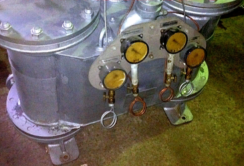
С некоторыми фотографиями работ по изготовлению Эжектора ЭО - 30м Вы можете ознакомиться в фотогаллерее выполненных работ.
В случае потребности Вашей организации в подобном оборудовании Вы можете обратиться к нам с заявкой, ответ с указанием стоимости оборудования мы направим Вам в течение 1 дня.